Playground reference
Painting electrodes and flying ions
This site is built around the Simulation Playground and many of the examples intend that you open the Playground up and try them out. Ion simulations are fun! That said, hopefully this site should be understandable even if you never touch the Playground.
As the Playground is not professional software, it may still have a few bugs or glitches. If you notice something strange or frustrating happening, consider reloading the page. Your work in the Playground will be erased but any issues should clear up.
Clicking on the Simulation Playground button opens up the playground. Clicking again closes it. The Playground is best interacted with wide-enough screens so that the two canvases (white and rainbow-colored) are side-by-side.
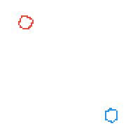
The buttons on the left-side of the Playground all deal with creating electrodes. Only four electrodes can be defined and each one has a color: red, green, blue, or brown. Each electrode also has a potential, a voltage, associated with it. By default, these voltages are 500 V, 1000 V, -500 V, and -1000 V, respectively.
Each electrode’s voltage can be changed to a value between -20,000 and 20,000 V. To change the value of an electrode, select it (red should be selected by default) and use either the slider or number input in the top-left corner of the Playground to change the voltage value.
You can paint with the selected electrode by clicking on the electrode canvas and dragging the cursor around.
Erasing an electrode can be done by selecting the button and painting with it.
Pre-built ‘paintings’ of electrodes can be loaded by clicking on one of the top buttons (e.g., , , etc.). Some of these these pre-built electrodes load advanced features.
When you have finished a painting or have loaded a pre-built set of electrodes, click on the blue ‘Refine Electric Fields’ button. The electric fields for the painted electrodes will be calculated and displayed in the rainbow-colored canvas on the right. Clicking the rainbow-colored canvas when no electric fields have been calculated is the same as clicking the blue ‘Refine Electric Fields’ button.
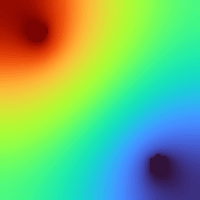
The rainbow colors of the electric fields represent different relative voltage values. Red means a high voltage, relative to all the other voltages in the electric field canvas. Blue represents a low voltage, relative to other voltages.
The absolute voltages of any area may be seen in the “status” update in the advanced tab.
Clicking on the electric field canvas after the fields have been calculated from the electrodes (also termed “refining” the electrodes) flies an ion. The start location of the ion is the location of the mouse cursor. The default mass of the ion is 100 Daltons (Da). The default charge is +1. The default x and y velocities are 0 mm per µs.
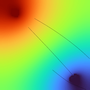
The field above has had three ions flown. Each ion’s trajectory is drawn as a black line on both the electrode and the electric field canvases. As the ions shown above were the default mass and charge (100 Da and +1 e, respectively) the ions are repelled from the positive (red) area and are attracted to the negative (blue) area. The simulation for an ion stops when the ion impacts (or “splats” against) an electrode or one of the four walls of the simulation. If the ion has a stable trajectory or moves very slowly, then the simulation will end after 400 µs (or 400,000 simulation steps).
Advanced
Dynamic electrodes and increased precision
Most of this website can be understood and enjoyed without touching the Advanced tab. If you are reading from the start, I encourage you to skip this section and come back to it later when you get to the “Dynamic simulations” section.
Like the Simulation Playground button, the Advanced tab is opened by clicking it and closed by clicking it again. The advanced tab has three purposes:
- To provide more information about the state of the simulation, such as exact voltages and ion locations
- To allow finer control of the flight of an ion or ions
- To enable basic dynamic behavior of electrodes (similar to “fast electrodes” in SIMION)
1. Extra information
The first of the additional information is the cursor status readback on the right-side that looks like:
x: 4 y: 197 volts: 4000.00. This area displays information related to the canvas the
cursor is currently on. For the electrode, electric field, and timeline canvases, this is the current x and y
position; the current x, y, and voltage; and the time within an ion’s simulation, respectively.
The second is the ion flight log. This is the gray, outlined box in the lower-right corner. When an ion is flown, a short entry indicating some information about its flight will be displayed in this box. This information can be useful for checking the accuracy of a simulation in the Playground versus one in SIMION, for recalling what some ion parameters might have been for a flight, or even for collecting samples of ion flights and performing statistical analyses (by copying and pasting the log into a program such as Microsoft Excel).
The ion flight log’s reported numbers are, in order:
- The mode of simulation termination – either a “Splat!” or a “Timeout!”
- The ion flight time in microseconds – 0 to 400 µs
- The mass-to-charge ratio (m/z) of the ion
- The ion’s start coordinates – in (x, y) form, where x and y are in mm
- The ion’s end coordinates – in (x, y) form, here x and y are in mm
- The ion’s starting velocity – in (x, y) form where x and y are in mm/µs
The third is . This button draws electric field lines on the electric field canvas. For visibility reasons, these lines are normalized and so only show the direction of the electric vector, not the magnitude.
2. Finer control
In the context of a simulation, ions have relatively few numbers that can define them: mass, charge, position, velocity. The x and y coordinates of an ion are provided by where the electric field is clicked. The simulated ion’s mass, charge, initial x, and initial y velocity can be supplied in the input boxes below.
Sometimes flying many ions with randomly determined parameters can be useful. The input boxes:
allow a number from 1 (default) to 50 ions to be flown with each “click” on the electric field canvas and provide randomness (from 0% to 100% random) for the position and velocity of ions, respectively. The charge and mass of ions is never randomized. The information about which ions were flown and where can be observed in the ion flight log,
Sometimes it is desirable to specify an exact, constant field at some location (for instance, the Playground assumes a field of 0 V everywhere). Constant fields can be simulated by electrodes that are transparent to ions, or are not “splattable”. To disable collisions with an electrode, untick the “splattable” checkbox in the Playground.
3. Dynamic electrodes
Most instruments that manipulate charged particles make use of dynamic electrodes that have voltages that change with time. The timeline canvas can be used to change the behavior – the voltage – of electrodes over the course of the 400 µs simulation. The ‘start’ of each ion’s flight will begin at time0 µs and end at time400 µs.
Clicking on the timeline canvas will cause one of the two range cursors – the vertical lines – to jump to the clicked location. Clicking somewhere else will cause the second range cursor to jump to that location. Each click will alternate one of the range cursors. In this way, a range can be easily defined between two time points.
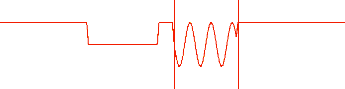
After defining a suitable time range, click one of the or buttons. The effect will be applied to the timeline. Now, during that time, the electrode will respond differently. By default, all electrodes are in a “high” state. “High” in this instance means that the electrode is activated, not that it has a positive voltage. An electrode in an “low” state normally applies 0 V. The “sine” state causes the electrode to oscillate between its high state and the inverse of its high state (so a -1000 V electrode would oscillate between 1000 V and -1000 V). To alter the timeline of a different electrode, select it. This will load its timeline that can be edited.
The “sine f” and “offset” fields can be used to to adjust the frequency of the sine wave or apply a constant offset to all the voltages of an electrode, respectively. With an offset of 1,000 V, an electrode normally set at -500 V would oscillate (with a sine applied) between 500 and 1,500 V. The electrode’s low state would be at 1,000 V and its high state would be at 1,500 V.
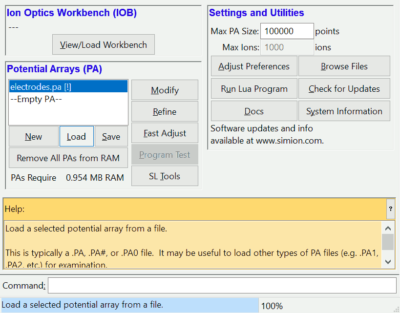
The finest level of control over your ion simulations comes from abandoning the Simulation Playground altogether and using another, production-quality program. To this end, the button saves and downloads your current electrode array to a SIMION “electrodes.pa” array of 200×200 points. This array can be imported into SIMION – SIMION will then need refine the electrodes to fly ions.
Importing your electrodes into SIMION is intended to help bridge the transition to using SIMION full-time! Another possible purpose for importing your electrodes is to verify that a simulation is accurate. The Simulation Playground is not intended to provide accurate simulations, and so its results might deviate from those of SIMION.